Database: a storage structure that provides mechanisms for recording, manipulating, and retrieving data. A collection of interrelated files—such as those relating to customers, their purchases, and their payments—is stored in a database
Database Management System (DBMS): is used to create and maintain the structure of a database, and then to enter, manipulate, and retrieve the data it stores.
Character: is the basic unit of data, and it can be a letter, number, or special symbol.
Field: represents one attribute or characteristic (for example, the name of a customer.
Record: A collection of fields about one customer (for example, name, address, city, state, and zip code) is called a record.
File: a ground of records about the same entity (such as customers or inventory items) is stored in a file.
Column: When creating the physical database, a field is commonly referred to as a column.
Row: a record is called a row.
Table: a file is known as a table.
A table is similar to a spreadsheet.
D A T A B A S E M A N A G E M E N T S Y S T E M (DBMS)
As mentioned earlier, a database is housed in a DBMS, which provides the functionality to create and work with a database. This functionality includes the following:
- Data storage: Manage the physical structure of the database.
- Security: Control user access and privileges.
- Multiuser access: Manage concurrent data access.
- Backup: Enable recovery options for database failures.
- Data access language: Provide a language that allows database access.
- Data integrity: Enable constraints or checks on data.
- Data dictionary: Maintain information about database structure.
To determine the most appropriate structure of fields, records, and files in a database, developers go through a design process. The design and development of a system is accomplished through a process that’s formally called the Systems Development Life Cycle (SDLC) and consists of the following steps:
- Systems investigation: Understanding the problem
- Systems analysis: understanding the solution to the previously identified problem
- Systems design: Defining the logical and physical components.
- System implementation: Creating the system
- Systems integration and testing: Placing the system into operation for testing.
- Systems deployment: Placing the system into production.
- Systems maintenance and review: Evaluating the implemented system.
Note:
A variety of SDLC models have been developed to address different development environments. The steps presented here represent a traditional waterfall model. Other models, such as fountain and rapid prototyping, involve a different series of steps.
When designing a database:
Ask the question: What information, or output, must come from this database?” or “What questions should this database be able to answer?” By understanding the necessary output, the designer can then determine what information should be stored in the database.
After that step (identifying the requirements of the database)
An entity-relationship model (E-R) is usually drafted to better understand the data to be stored in the database.
An entity is any person, place, or thing with characteristics or attributes that will be included in the system.
An E-R model is a diagram that identifies the entities (customers, books, orders, and such) in the database, and it shows how the entities are related to one another.
Note:
An E-R model is also called an entity-relationship diagram (ERD).
In an E-R model, an entity is usually represented as a square or a rectangle. As shown in Figure 1-3, a line depicts how an entity’s data relates to another entity. If the like connected the two entities is solid, the relationship between the entities is mandatory. However, if the relationship between two entitles is optional, a dashed line is used.
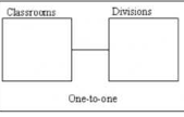
One-to-one: In a one-to-one relationship, each occurrence of data in one entity is represented by only one occurrence of data in the other entity.
For example, if each classroom is assigned to only one academic division, a one-to-one relationship is created between the classroom and division entities. This type of relationship is depicted in an E-R model as a simple straight line.
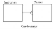
One-to-many: In a one-to-many relationship, each occurrence of data in one entity can be represented by many occurrences of the data in the other entity.
For example, a class has only one instructor, but an instructor might teach many classes. A one-to-many relationship is represented by a straight line with a crow’s foot at the “many” end.
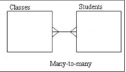
Many-to-many: In a many-to-many relationship, data can have multiple occurrences in both entities. For example, a class can consist of more than one student, and a student can take more than one class. A straight line with a crow’s foot at each end indicates a many-to-many relationship.
Note: The notations in the sample E-R models in this chapter reflect only one way of diagramming entity relationships. If you’re using a modeling software tool, you might encounter different notations to represent relationships. For example, Microsoft products typically represent the many side of a relationship with the infinity symbol (∞). In addition, some modeling tools automatically add the common fields or foreign key columns needed as relationships are defined.
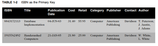
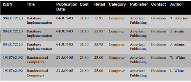
When a record contains repeating groups (that is, multiple entries for a single column), it’s considered unnormalized. First-normal form (1NF) indicates that all values of the columns are atomic—meaning they contain no repeating values. To convert records to 1NF, remove the repeating values by making each author entry a separate record, as shown in Table 1-3.
When more than one field is used as the primary key for a table, the combination of fields is referred to as the Composite primary key.
When there are two fields that are not supposed to be there, a problem known as partial dependency can occur.
Partial dependency means the fields contained in a record (row) depend on only one portion of the primary key.
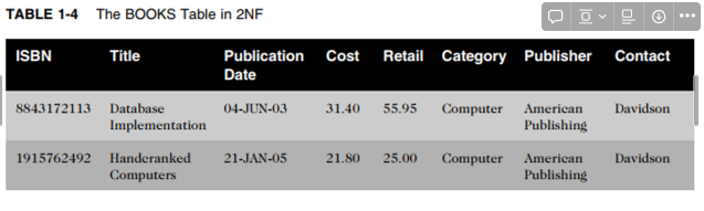
The simplest way to resolve a partial dependency is to break the composite primary key into two parts—each representing a separate table. In this case, you can create a table for books and a table for authors. By removing the partial dependency, you have converted the BOOKS table to second-normal form (2NF), as shown in Table 1-4.
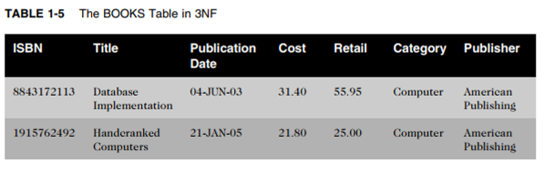
Now that the BOOKS records are in 2NF, you must look for any transitive dependencies. A transitive dependency means at least one value in the record isn’t dependent on the primary key but on another field in the record. In this case, the contact person from the publisher’s office is actually dependent on the publisher, not on the book. To remove the transitive dependency from the BOOKS table, remove the contact information and place it in a separate table. Because the table was in 2NF and had all transitive dependencies removed, the BOOKS table is now in third-normal form (3NF), as shown in Table 1-5.
There are several levels of normalization beyond 3NF; however, in practice, tables are typically normalized only to 3NF. The following list summarizes the normalization steps explained in this section:
- 1NF: Eliminate all repeating values and identify a primary key or primary composite key.
- 2NF: Make certain the table is in 1NF and eliminate any partial dependencies.
- 3NF: Make certain the table is in 2NF and remove any transitive dependencies.


Leave a comment